Astra Tech
BioManagement Complex Astra Tech
BioManagement Complex
|
 MicroThread MicroThread
MicroThread™ is the minute thread design on the neck of the Astra Tech implants, introduced as early as 1991. Scientific articles present the ability of MicroThread to ensure positive biomechanical bone stimulation and to maintain marginal bone levels in the long term. Summarized on the following pages, you will find articles about the continuous follow-up of the MicroThread.
 The implant thread as a retention element in cortical bone the effect of thread size and thread profile: a finite element study The implant thread as a retention element in cortical bone the effect of thread size and thread profile: a finite element study
 Purpose: The purpose of this study was to evaluate
the effect of different thread profiles and dimensions
on the interfacial bone stress of an idealized axially
loaded implant using finite element analysis (FEA 7
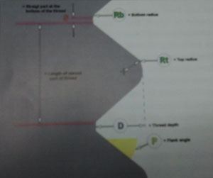
Materials and Methods: The Ansys (V5.0) program was employed for the FEA utilizing the theory of elasticity. A 3.5 mm screw shaped implant of infinite length (c.f. Astra Tech) was model in cortical bone with the threads modelled as a bead whose profile and dimension could be varied. Thread profile parameters were depth (D), top radius of curvature (Rt), bottom radius of curvature (Rb) flank angle (P), and the straight section between the threads (S). The length of the base of the thread was designated (L). Purpose: The purpose of this study was to evaluate
the effect of different thread profiles and dimensions
on the interfacial bone stress of an idealized axially
loaded implant using finite element analysis (FEA 7
Materials and Methods: The Ansys (V5.0) program was employed for the FEA utilizing the theory of elasticity. A 3.5 mm screw shaped implant of infinite length (c.f. Astra Tech) was model in cortical bone with the threads modelled as a bead whose profile and dimension could be varied. Thread profile parameters were depth (D), top radius of curvature (Rt), bottom radius of curvature (Rb) flank angle (P), and the straight section between the threads (S). The length of the base of the thread was designated (L).
A 100% bone-to-implant contact was assumed permitting frictionless sliding and only compressive stresses transferred between implant and bone. The bone was modelled to be isotropic and homogenous with a Poisson's ratio of 0.3. Test analyses were performed to confirm that a higher than normal modulus could be applied without affecting the calculated stresses. This was necessary to avoid the abruptness of stiffness to complete rigidity, which had to be bridged by the contact elements between the implant and bone. An axial load of 5 N/mm X implant length was applied and the data captured was the peak tensile stress and the peak compressive stress in the bone as a function of the values of the differing thread profiles. The element mesh was made up of 1129 elements, each comprising four nodes. Each node had two degrees of freedom.
Results: In all the calculations for the different thread profiles the peak tensile stress was located outside the top of the thread. The peak compressive stress was located on the lower slope of the top radius of curvature except for large flank angles combined with long value for S, when the peak compressive stress was located close to the bottom of the thread flank.
Using convergence analysis it was determined that a thread depth of 0.1 mm was as effective as a thread depth of 0.4 mm. As such very small threads could in fact prove remarkably effective at distributing functional stresses. In addition a low ratio between the top radius of the curvature, Rt and thread depth, D should be avoided since deep sharp threads gave rise to deleterious stress concentrations.
With regard to the distance between threads it appears that the influence of this parameter is dependant on other factors, as such for a continuous thread profile where the distance S is extremely small, the Rt and p influence the stresses. In such a case a value for Rt equal to 0.4-1.0 times the thread depth and a value for p equal to 40-60 degrees yields low values for tensile stress. When the threads are separated and the distance S is large the flank angle should be approximating 0 degrees, since for large flank angles high tensile stresses are recorded where the threads are separated by an increasing distance S.
Finally with respect to Rb it was assumed that a value 0.1 times the thread depth was optimal since the stresses were not located in this area.
Discussion: In the current study the model of a stiff, infinitely long, axially loaded implant embedded in homogenous, isotropic, cortical bone, with a frictionless interface and 100% bone-to-implant contact is far from clinical reality. However, the model was established to allow the distribution of stress in the bone to be identical outside all threads thereby allowing a comparison between threads of different size and profile. In addition the attempt to understand the pure effect of thread profile and dimension on bone stresses warrants this idealistic approach. Its findings then require clinical validation.
The FEA results indicated that the thread profile did influence the stress peaks in bone. In addition it appeared that subject to a favourable profile, very small microthreads were equally as effective as large threads. In addition it could be stated that a small value for the top radius of the curvature, Rt, is to be avoided and a large value for the section between the threads, S is unfavourable for most thread profiles as is a large value for the bottom radius of the curvature, Rb. |
|
|